Radio inside, Antennas outside. How do you make the two connect in the most efficient manner?
So, as with most Ham radio operators, I had the dilemma of the proper way to bring the antenna coax into the shack. The goal was to move the the signal to and from the radio with the lowest loss possible but yet keeping the house as sealed as possible from the weather elements and unwanted pest. I also wanted to keep the modification as ”non-permanent” as possible; Not because I didn’t have the intention of remaining in the hobby, but because I wasn’t sure if the basement would be the permanent location of the radio station. After asking a few friends who have already conquered this obstacle, I found that I wasn’t as fortunate to have an abandoned dryer vent or other previously established receptacle that would allow for the direct entrance of coax with little to no modification. That being the case, I was in search of my own solution.
Drilling through 8″ block, wall board and then exterior brick for a really long barrel connector wasn’t my first choice. I could have used the same entrance as the satellite dish coax and just ran the feed lines into the radio room from there. But that would have added 50-100 feet of more feed line per antenna that I wasn’t willing to buy nor accept the loss for the longer runs. With the placement of my antennas, I was able to route the feed lines in a way that they would drop off of the roof and fall directly in front (or very close to) a window that led into my radio room.
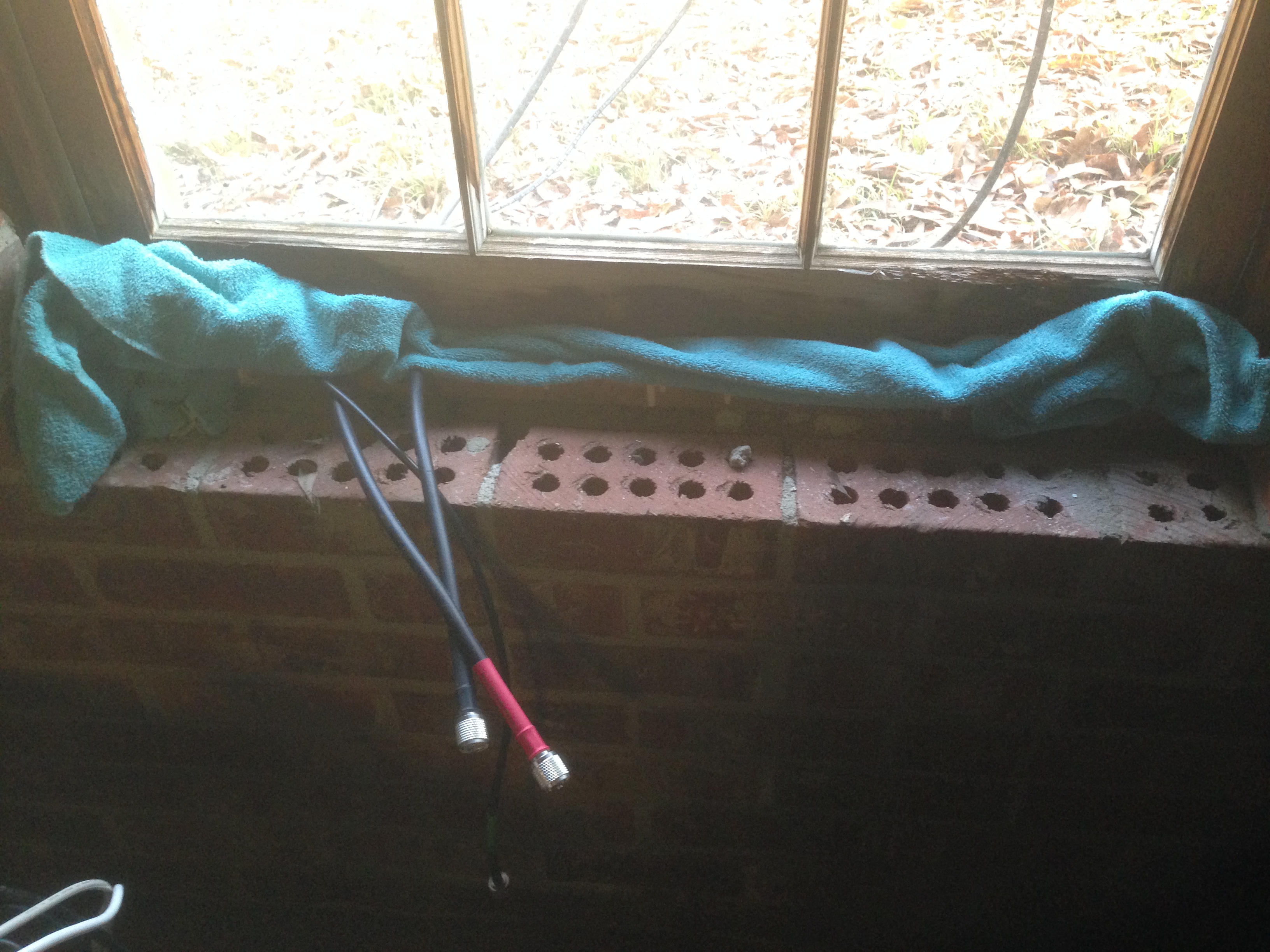 As a temporary fix, I simply opened the window and ran the coax into the house. I folded a towel and laid it horizontally on the bottom of the window frame to pad the coax and to provide some draft protection. This was only a temporary fix for several reasons. To maintain the security of the house, I had to reverse the operation after I was QRT so that the window could be secured. As thoughtful as the towel buffer appeared, it was no match for 10 degree (F) weather and 25 MPH winds.
After some research on the internet, I came across the idea of a Window Feed Through Panel. MFJ makes several feed through panels with different configurations of connections. Most of them have PL-259′s and others have balanced line, random wire, type F and type N connections. I liked the concept of the feed through panel but I didn’t like the price of them. I looked into making one with some barrel connectors and other items that I had laying around the workshop. Just pricing the barrel connectors, I wasn’t going to be able to make it as cheap as I was hoping.
Within a few days, I found a fellow ham radio operator post a few items on a local reflector about items that he was looking to sell. One of them was a MFJ 4603 for $50! It was slightly used but had no serious signs of wear on it. It was cut to a narrower window that mine but I figured that I could play around with it and make it work for my purpose.
Here is the process that I went through to modify it for my needs.
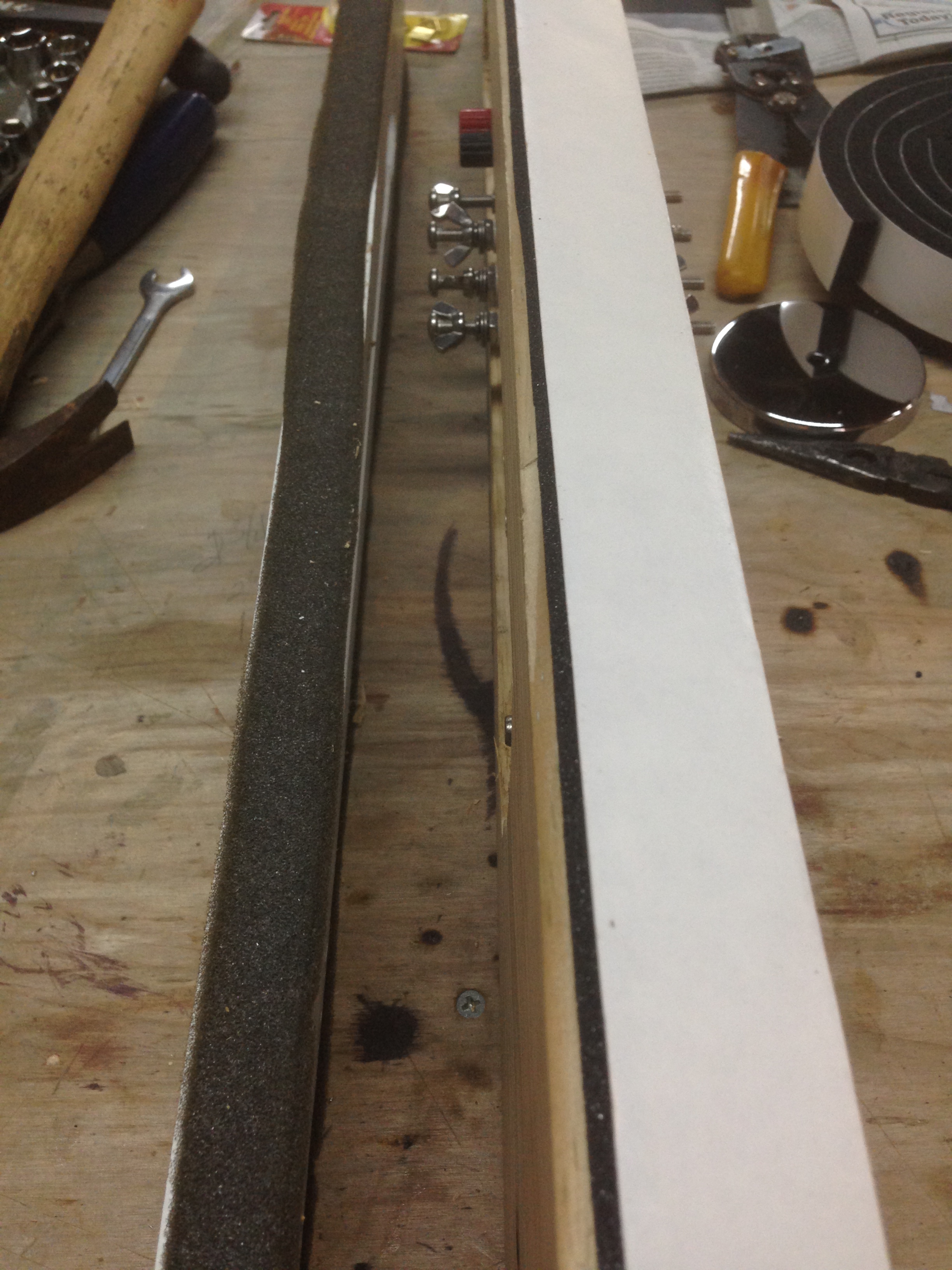 Here you can see here that the original panel as built by MFJ is only 1/2 inch thick. As this would work in most applications, I wanted a board that would be as wide as my window. So I simply used the hardware from the MFJ panel and installed it onto a board that I had already cut to fit. I went ahead a cut an angle on the bottom side to match the slope of the window base. ( you’ll see a picture of that below)
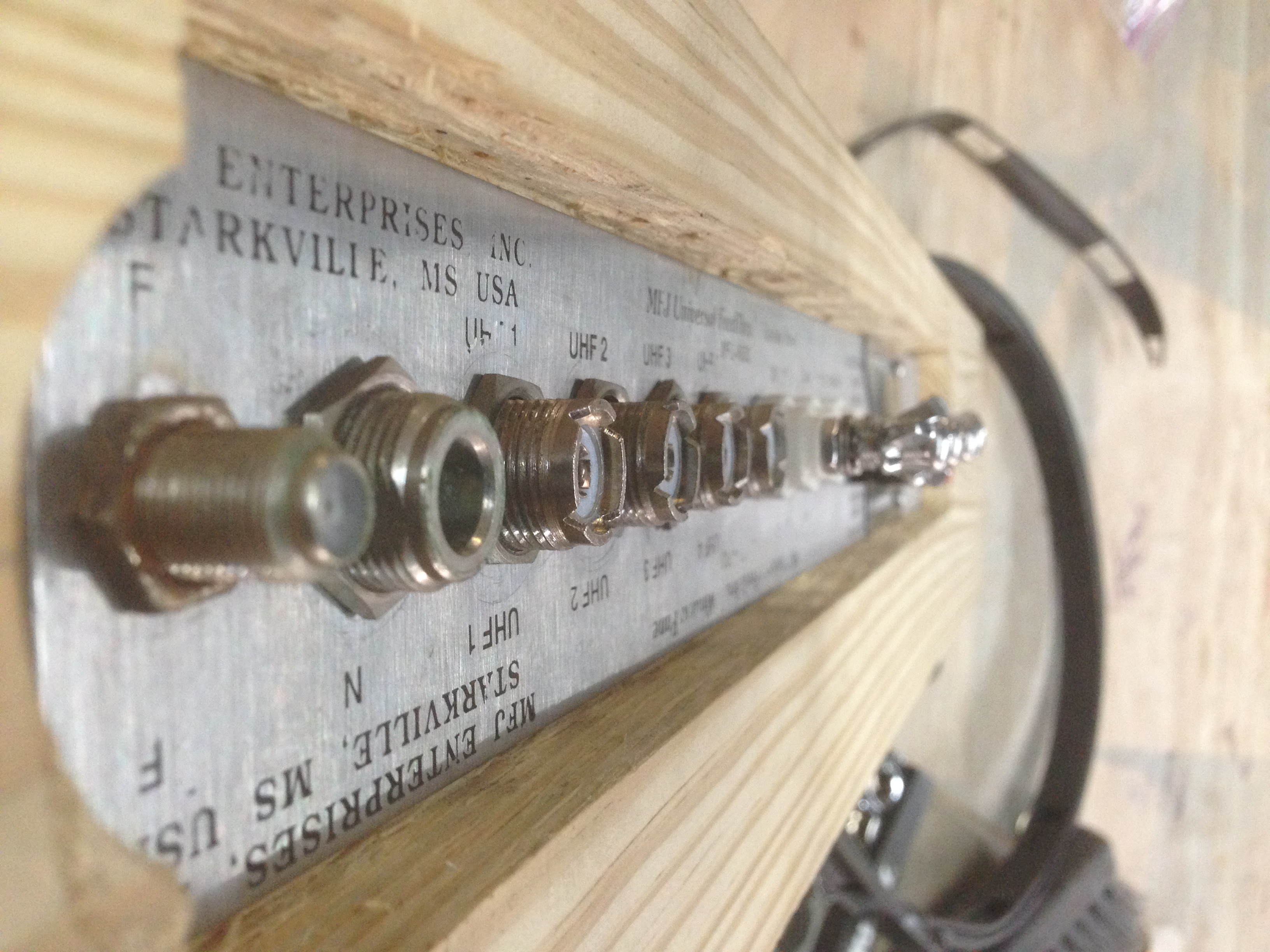
I disassembled the parts of the old panel and drilled holes in the new piece of wood to match the openings that I needed. (See pic) This was rather easy using the faceplate as a template. A drill press will help to ensure that your holes are at 90 degrees. This is important because your faceplate on the opposite side needs to match. The MFJ panel had one long void that ran the entire length of the board rather than the individual holes. I chose to create the individual holes in the panel for structural integrity and for the insulation for the individual components. I do not know if really matters but I feel it is now a better built panel.
One problem that I ran into was that the connectors for the MFJ panel were designed to fit the narrow board instead of the new thicker board that I had made. The insulated post could have been modified with relatively inexpensive bolts and such to allow for the thicker stock but I would have still had to purchase the longer barrel connectors that would have more than doubled the cost of this project. This problem was solved by recessing one side of the panel into the wood to match the thickness of the old board. (See pic) I just used forstner bits on my drill press to get rid of most of the wood and make the recess even across the board. I choose to face the recessed side to the outside to provide a little more protection from the weather. I knew this wouldn’t totally protect the connectors from water but I figured it would be more beneficial outside that it would be inside.
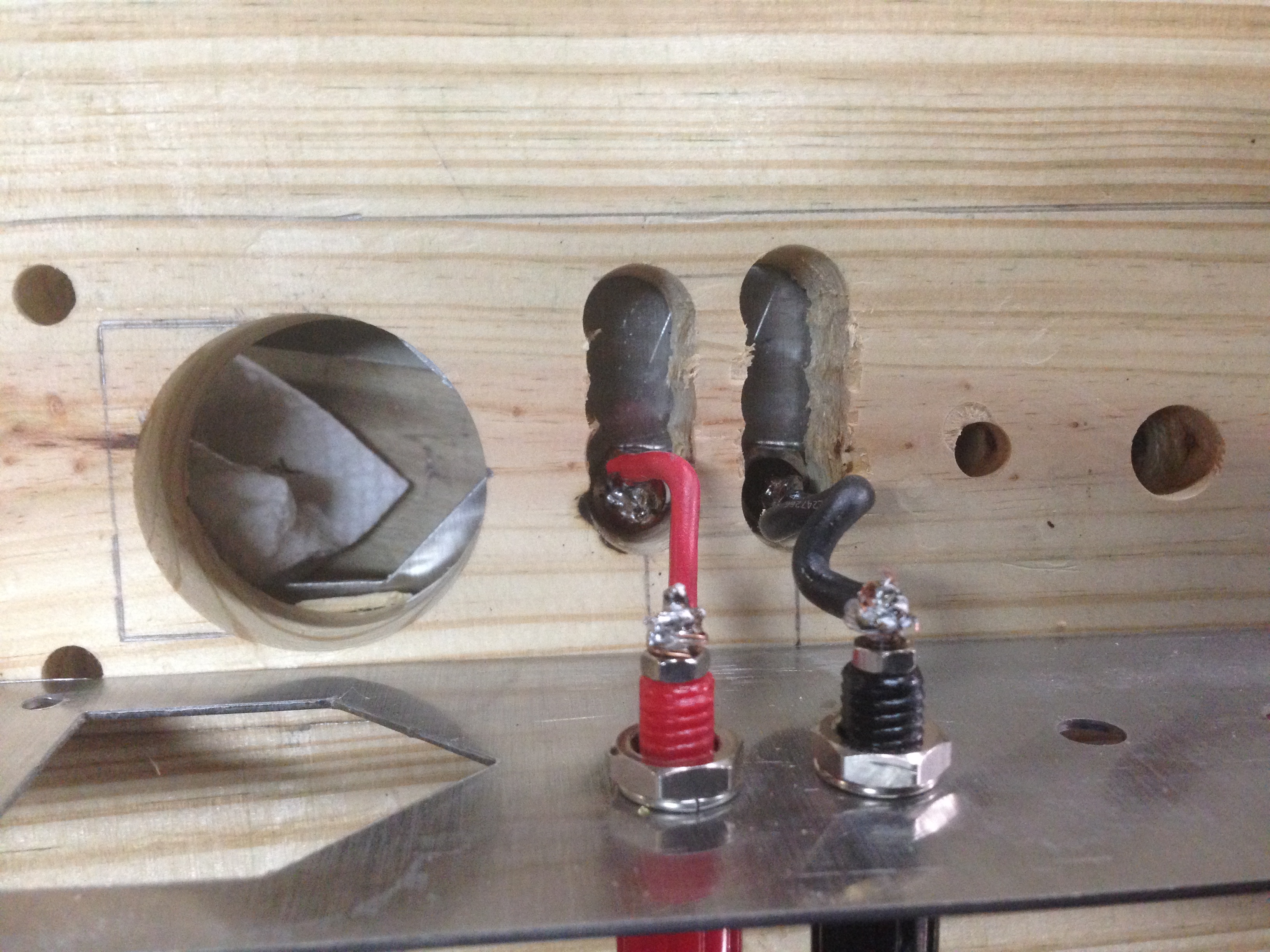
This particular panel came with DC/AC power connections to run power outside of the shack. As you can see here, the connectors weren’t run straight through the panel but they were offset to allow for a connecting medium to be stored. I simply found some spare 16 gauge wire and soldered it to the connectors.
I had some 1 1/4″ weather striping left over from a previous project that I applied to the top and bottom edge for a better seal. This simply was a peel and stick application that seemed to work well.
After the weather striping was in place, I simply dropped the new panel in place, closed the window, connected my antennas to the outside and then ran jumpers from the inside of the panel to the appropriate equipment. Just as a side note, I priced the jumpers buying them commercially and they were in the neighborhood of $20-$25 each. Being that I now needed several of them, I tried my hand at making them myself. The coax was less than $1 per foot and the good PL-259’s were around $3 each (probably cheaper in bulk at the local hamfest). I saved a TON of money doing it myself rather than buying the pre-made ones. AND I was able to customize the lengths of the jumpers rather than using all 3′ runs. If you don’t already know how to make your own jumpers, get with an elmer and learn a new skill! It will not only save you some money but it will be a valuable skill in the event that you have a failure in the field!
After all was in place and working well, I have now created the issue of home security. I now had a window that was unsecured with rather expensive equipment just inside. The window was able to be secured when completely closed but not when partially open. To solve this problem, I cut notches in 2 pieces of 2 by 4’s to wedge in between the now partially open window and the top of the window frame. (See pic) I wanted a snug fit so I cut the boards a little long and wedged them in the gap. This allowed me to apply downward pressure on the window to seal the weather stripping and to maintain a window that wasn’t vulnerable to a gentle tug from he outside. Given the fact that the window is generally the most insecure feature of your house, I feel this at least secured this window as well, of not better, than it was before the project began. Other security measures can be taken, not just for this one, but for all windows but that is for another blog on another day.
Below are a few thumbnails of the pictures that I took during the project. Just click on any of them for a full sized version of the image.


Nice job. I plan to make one using PVC 1×4 board which should serve as an insulator between fittings. Maybe drill two holes for coax bulkheads (I only plan to use one at the moment for my 6M/2M/440 vertical above the radio room), some all-thread bolts and wing nuts for one or two balanced feedlines (my main reason to even do this), a ground bolt and a random wire bolt (all-thread also and some wingnuts there, too).
Your thoughts on this since you’ve give this a lot of thought before modifying an MFJ window pass through panel to fit what looks like a much wider window?
My window opening is less than 30 inches inside the frame (probably 28.5 inches, can’t get to it to measure as the storage room needs stuff moved around to make it into a ham shack on a good computer desk).
I hope to do the clean out of the storage/laundry room this weekend and have the MFJ 80M-6M doublet with open wire feed line up this coming week to actually get some use out of my equipment.